What is a disc spring?
A disc spring is a conical ring shell designed to be loaded in the axial direction either statically or vibrationally. Generally, the load is transmitted via the upper and inner edge and the lower and outer edge. Disc springs can be used as a single spring or as a stack where single disc springs or spring packages consisting of several springs can be alternately layered.
| Formula | Unit | Label |
| δH = δO – δU | N/mm² | Continuous stroke strength |
| δh | N/mm² | Stroke voltage, assigned to the working stroke for disc springs with oscillating stress |
| δU | N/mm² | Calculated undervoltage for disc springs with oscillating stress |
| δO | N/mm² | Calculated High Tension for disc Springs with oscillating Stress |
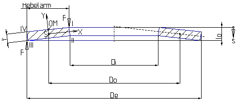
| δOM δI δII δIII δIV | N/mm² | Calculated stress at the points OM,I,II,III and IV according to Fig. 1 |
| σ | N/mm² | Calculated stress |
| δ = De / Di | Diameter ratio | |
| t | mm | Thickness of the single disc |
| s | mm | Spring travel of the single disc spring |
| l0 | mm | Height of the unloaded single disc |
| h0 | mm | Clearance height at unloaded single disc (calculated variable h0 = l0-t) |
| F | N | Spring force of the single disc |
| Do | mm | Diameter of the inverted center circle |
| Di | mm | Inside diameter |
| De | mm | Outside diameter |
In comparison with other spring types, the disc spring has a number of advantageous characteristics including the following:
- Disc springs can absorb large forces in small installation spaces.
- Depending on the dimensional ratios, the spring characteristics can be linear or degressive and can also be progressive through appropriate arrangement.
- The almost endless possible combination enables to vary the characteristic curve or the column length within broad Limits.
- High durability under dynamic loading if the spring is properly dimensioned.
- The rotational symmetrical form ensures that the force is concentrically transferred.
Thanks to these outstanding characteristics, the disc spring has been introduced into nearly all areas of technology during the last decades.
The following two standards are applicable to disc springs: DIN EN 16984 (formerly DIN 2092) disc spring calculation and DIN EN 16983 (formerly DIN 2093) disc spring dimensions and quality requirements.
These standards provide the basis for our production. The calculation procedure standardized according to DIN EN 16984 (formerly DIN 2092) dates back to a work of J.O. Almen and A. László and has proven successful in practice for many years.
The DIN EN 16983 (formerly DIN 2093) standard includes three dimensional series of disc springs varying in the ratios between outer diameter / thickness and clear height / thickness as well as comprehensive quality requirements and standards for quality, tolerance limits, material, allowable stress, allowable re-positioning, guide clearance and inspection of disc springs.
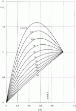
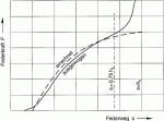
The ratio ho/t is characteristic of the curvature of the spring characteristic curve (Fig. 2).
For ho/t < 0.4 the characteristic curve is almost linear, with increasing ho/t ratio degressivity increases.
For ho/t = √2 the characteristic curve has an almost horizontal curve part (at s = ho it has a horizontal tangent).
This allows the development of springs having horizontal characteristic curves where the force rises only marginally despite increasing deflection. For longer spring columns, however, springs with ho/t ? 1.3 are not suitable due to the fact that single springs within the column can deflect irregularly and be overloaded. Such springs should, therefore, only be used as single springs.
Because of the dependence of the curvature of the characteristic curve on the ratio ho/t, the characteristic curve of disc springs with similar dimensions change when such disc springs are stamped to different heights. Conversely, at the same height ho, a thin disc will have a larger curvature of the characteristic curve than a thick disc.
For the normal arrangement of disc springs a progressive increase in the spring force occurs at deflections of s > 0.75 ho which deviates from the calculated value. This results from the shift in the force application points to smaller lever arms, because the disc springs roll on each other or on the abutment face. Therefore, it is recommended that only approx. 75-80 % of the spring deflection is utilized.
For this reason, the spring forces are only indicated at s = 0.75 ho (Fig. 3) in DIN EN 16983 (formerly DIN 2093).
Static design
Static or rarely alternating loading occurs when:
- disc springs are only statically loaded without load changes;
- disc springs are subject to occasional load changes at longer time intervals and less than 10.000 cycles during the intended lifetime.
Generally, the overall height lo of a disc spring is designed as to ensure that the spring can be loaded with static or rarely alternating loads without decreasing the dimension lo beyond the allowable tolerances.
Allowable loading
The stress at the position OM shall approximately correspond to the yield strength of the material being processed. To spring steels according to DIN EN 10132-4 (and DIN EN 10132-1) following shall apply:
OM -1600 N/mm2.
For other materials, the relevant values for the yield strength have to be taken into consideration. Where appropriate, slight re-positioning is possible.
Dynamic loading occurs in disc springs when the load continuously changes between a preload deflection s1 and a deflection s2.
Under the influence of a stress range ?h dynamically loaded disc springs can be classified into two groups according to their lifetime (see also DIN50100).
a)Disc springs with longer lifetime. These disc springs are expected to endure
2 x 10⁶
load changes and more without fracture. If a significantly longer lifetime of disc springs is required, please contact us. Accurate information may possibly only be provided by an endurance test.
b)Disc springs with limited lifetime. These disc springs are expected to achieve a limited number of load cycles in the range of fatigue strength
104 N < 2 x 10⁶
before fracture occurs.
Field of cross sections applicable to the fatigue fracture
The calculated tensile stresses at the lower surface of the disc spring are applicable to disc springs with dynamic loading because fatigue fracture always emanates from here.
Depending on the dimensional ratios ? = De / Di and ho/t and the relative deflection s/ho the largest stress range may occur at position II as well as at position III. Whether position II or III is applicable, please refer to Fig. 4.
Minimum preload deflection to prevent cracking
After heat treatment the disc springs are preset which causes a plastic deformation in the range of cross section I and results in residual tensile stresses in the unloaded spring. Under loading conditions a change between tensile and compressive stress occur which result in cracking under dynamic loading. To prevent cracking, the residual tensile stresses have to be compensated by appropriate preload.
Therefore, dynamically loaded disc springs should be preloaded to a minimum of s = 0.15 – 0.20 ho.
Allowable loading
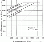
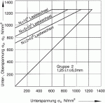
The stresses calculated for the working range of the spring are compared with the fatigue limit and fatigue life diagrams (Fig. 5 and 6) indicating the reference values of fatigue strength ?H for # for dynamically loaded disc springs that are not shot peened.
N 2 x 10⁶
load changes and the fatigue life for
N = 105
and
N = 5 x 10⁵
load changes depending on the minimum stress ?U. Intermediate values applicable to other number of cycles can be estimated.
The diagrams as shown to the right (Fig. 5 and 6) illustrate two of the product groups according to DIN EN 16983 (formerly DIN 2093).
These groups are classified according to their thickness as follows:
Group 1: t less than 1.25 mm
Group 2: t = 1.25 mm – 6 mm
The fatigue limit and fatigue life diagrams have been obtained from laboratory tests using test equipment with uniform sinusoidal loading and determined by statistical evaluation on the basis of an expected survival probability of 99 %.
Consequently, fatigue fracture may result in early failure of 1 % of a large number of springs.
The diagrams are applicable to single disc springs and spring columns comprising up to 10 alternately arranged single disc springs working at room temperature with surface-hardened and properly processed internal and external guides as well as a minimum preload deflection s1 = 0.15 – 0.20 ho.
In practice it has to be taken into account that the type of loading differs in many cases from an approximate sinusoidal oscillation. With alternating shock loading and as a result of natural vibrations, the real load of the material can be significantly higher than the calculated load. With these cases of load, the values of the diagrams may only be used taking into account appropriate securities.
Adequate fatigue strength values are not yet available for spring columns with more than 10 or multiple parallel layers of single disc springs and if other unfavourable factors arise including thermal or chemical influences.
In such cases, additional safety factors have also to be taken into account. Please contact us for further consultation.
